Our blog
Full HD is here
Well, let me answer all your emails at once.
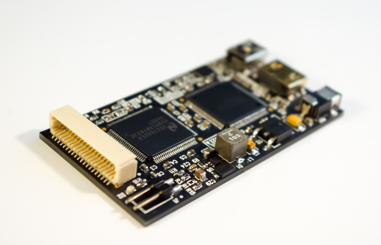
Meet our new Full HD HDMI converter:
- slim compact design - 6.5x3.5x0.7 cm only
- flat bottom side - can be fixed right on bottom side of LCD panel
- HDMI to Dual-LVDS converter for resolutions up to 1920x1200, 16M colors
- mini HDMI input for video
- slim-profile power connector (OD=2.6mm, ID=0.65mm, positive central pin)
- mini USB connector for easy firmware update, and for programmable backlight control from user application (yes, we did it!)
- integrated backlight controller can generate up to 37V/1.5A right on board for most LCDs up to 23"
- input for external ambient light sensor for automatic brightness control
- easy programmable EDID block (through USB)
- new universal 40-pins LVDS connector
New dual-LVDS HDMI converter for FullHD applications
We will offer this converter as a standalone solution, and will also offer in bundle with our new FullHD+ LCD:
FullHD+ 10" LCD specifications:
- Display: 10” full-color a-Si TFT with IPS technology
- Native resolution: 1920x1200 pixels
- Aspect ratio: 16:10 (widescreen)
- Display colors: 16 millions (8-bits per color)
- Panel dimensions: 229.5mm (H) x 149.2mm (V)
- Weight: 138 grams
- Power consumption: 3W (typ)
- Brightness: 400 cd/m2 (nits)
- Contrast ratio: 800:1
- Viewing angle: 89 deg (all directions)
- Works well with RaspberryPi (original and B+), actually it's the highest possible resolution supported by RasPi
New FullHD+ 10" LCD with integrated HDMI converter

That's not all, folks! Lets continue tomorrow with news. Stay tuned!
How to program custom EDID data in HDMI converter
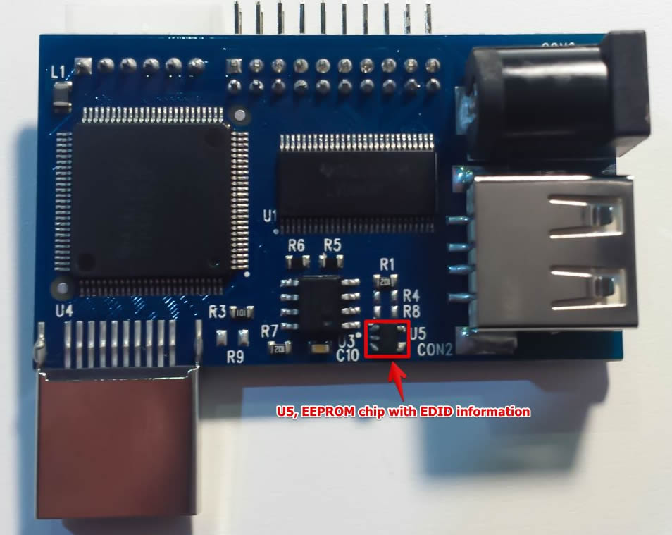
EDID stands for Extended Display Identification Data (EDID), and is a data structure provided by an LCD to describe its capabilities and supported resolutions to a video source (RaspberryPi, PC, Android stick, etc.) EDID is stored in EEPROM memory chip with I2C interface on LCD receiver side. In our case this is small chip U5:

We ship our HDMI converters with pre-programmed EDID data for our standard LCD panels (1280×800 for single-LVDS, and 1920×1200 for dual-LVDS converter). If you want to use it with different LCD panel and different resolution, then you should update EDID information stored in EEPROM chip. Fortunately, this is not difficult procedure, and it will not require any special hardware tools. All you need is Linux powered PC or board (like RasPi) with HDMI output and keyboard to type in terminal commands. So, run Linux, open Terminal, connect our HDMI converter to HDMI output of PC, and power it with external power supply. Others cables are not required.
- First of all, lets install required tools. We will need Python SMBus library to read/write data to I2C bus, and EDID decode tools to represent EDID data in human-readable form:
1sudo apt-get install python-smbus edid-decode
- Then we should download edid-rw utility:
1git clone https://github.com/bulletmark/edid-rw
- And write-edid script that I wrote to simplify update process:
1git clone https://github.com/ChalkElec/write-edid
- Activate i2c-dev kernel module to get access to I2C bus:
1sudo modprobe i2c-dev
- Now we should find which I2C bus is used by our HDMI adapter. The simplest way is to try bus numbers one by one with command like:
1sudo ./edid-rw 0 | edid-decode
- In my case I found HDMI adapter on bus #3:
1sudo ./edid-rw 3 | edid-decode
I got output like this:
1
2
3
4
5
6
7
8
9
10
11
12
13
14
15
16
17
18
19
20
21
22
23
24
25
26
27
28
29
30
31
32
33
34
35
36
37
38
39
40
41Extracted contents:
header: 00 ff ff ff ff ff ff 00
serial number: 30 e4 45 03 00 00 00 00 00 15
version: 01 04
basic params: 90 16 0e 78 02
chroma info: e8 87 96 5a 55 95 28 22 51 55
established: 00 00 00
standard: 01 01 01 01 01 01 01 01 01 01 01 01 01 01 01 01
descriptor 1: 4c 1d 00 ec 50 20 18 30 40 30 57 00 d9 88 00 00 00 1b
descriptor 2: 16 12 00 80 50 20 16 30 30 20 47 00 d9 88 00 00 00 1b
descriptor 3: 00 00 00 fe 00 43 33 47 52 4e 80 31 30 31 57 58 31 0a
descriptor 4: 00 00 00 00 00 00 41 32 a8 00 00 00 00 01 01 0a 20 20
extensions: 00
checksum: 9a
Manufacturer: LGD Model 345 Serial Number 0
Made week 0 of 2011
EDID version: 1.4
Digital display
6 bits per primary color channel
Digital interface is not defined
Maximum image size: 22 cm x 14 cm
Gamma: 2.20
Supported color formats: RGB 4:4:4
First detailed timing is preferred timing
Established timings supported:
Standard timings supported:
Detailed mode: Clock 75.000 MHz, 217 mm x 136 mm
1280 1344 1392 1516 hborder 0
800 805 812 824 vborder 0
+hsync -vsync
Detailed mode: Clock 46.300 MHz, 217 mm x 136 mm
1280 1328 1360 1408 hborder 0
800 804 811 822 vborder 0
+hsync -vsync
ASCII string: C3GRN€101WX1
Manufacturer-specified data, tag 0
Checksum: 0x9a
EDID block does NOT conform to EDID 1.3!
Missing name descriptor
Missing monitor rangesI can recognize it by Manufacturer string that contains “LGD” – short code of LG Display company, and by resolutions numbers “1280” and “800” in Detailed mode string. For dualLVDS converter resolution will be 1920×1200
- Now we know I2C bus number and can program another EDID information to our HDMI adapter. But be careful to state correct bus number on the next step. Better check twice output on previous step, then check once again. If you state wrong I2C bus number, you can accidentally overwrite another I2C EEPROM with wrong data (like EDID information of main LCD panel of your notebook).
- We use the following command to update EDID with information from file edid_auo14.bin (in our case this is EDID information for our 14″ AUO panel):
1sudo ./write-edid.sh 3 edid_auo14.bin
- Let’s check that EDID has been updated:
1sudo ./edid-rw 3 | edid-decode
We should have the following output for 14″ EDID data:
1
2
3
4
5
6
7
8
9
10
11
12
13
14
15
16
17
18
19
20
21
22
23
24
25
26
27
28
29
30
31
32
33
34
35
36
37
38
39
40
41Extracted contents:
header: 00 ff ff ff ff ff ff 00
serial number: 06 af 3c 10 00 00 00 00 00 16
version: 01 04
basic params: 90 1f 11 78 02
chroma info: 10 b5 97 58 57 92 26 1e 50 54
established: 00 00 00
standard: 01 01 01 01 01 01 01 01 01 01 01 01 01 01 01 01
descriptor 1: ce 1d 56 d2 50 00 26 30 10 10 3e 00 35 ad 10 00 00 18
descriptor 2: df 13 56 d2 50 00 26 30 10 10 3e 00 35 ad 10 00 00 18
descriptor 3: 00 00 00 00 00 00 00 00 00 00 00 00 00 00 00 00 00 00
descriptor 4: 00 00 00 02 00 0c 39 cc 0d 3c 64 0f 0c 1b 6f 20 20 20
extensions: 00
checksum: 0d
Manufacturer: AUO Model 103c Serial Number 0
Made week 0 of 2012
EDID version: 1.4
Digital display
6 bits per primary color channel
Digital interface is not defined
Maximum image size: 31 cm x 17 cm
Gamma: 2.20
Supported color formats: RGB 4:4:4
First detailed timing is preferred timing
Established timings supported:
Standard timings supported:
Detailed mode: Clock 76.300 MHz, 309 mm x 173 mm
1366 1382 1398 1576 hborder 0
768 771 785 806 vborder 0
-hsync -vsync
Detailed mode: Clock 50.870 MHz, 309 mm x 173 mm
1366 1382 1398 1576 hborder 0
768 771 785 806 vborder 0
-hsync -vsync
Manufacturer-specified data, tag 0
Manufacturer-specified data, tag 2
Checksum: 0xd
EDID block does NOT conform to EDID 1.3!
Missing name descriptor
Missing monitor rangesAs you can see, Manufacturer string now contains “AUO”, and Detailed mode has resolution 1366×768, so we did everything right, and now we can use HDMI adapter with another panel (14″ AUO in our example)
Urgent update on May orders
We have to delay shipment of most May orders for around 2 weeks and ask for return selected shipped orders. The reason is non-stable (counterfeit?) power switch ICs supplied by one of our Taiwan supplier. Boards passed our standard QC tests, and we already shipped around 40 orders, when got several notes from customers about non-stable work. Additional tests made in our lab showed that problem arises when board is powered for more than 3-5 minutes – power switch gets hot and unstable. As a result, LCD backlight starts flicker. Here are steps that we did regarding this problem:
- We placed on hold shipment of ready orders. Your orders will be shipped in around 2 weeks counting from now. New ICs has been ordered and should arrive to us early next week. Then it will take several days to rework boards, make new tests, and prepare orders for shipment
- We wrote RMA emails to customers with already shipped orders that can have this problem. If you received email with RMA request, then please read it carefully, test your board/bundle for at least 10 minutes, and let us know about results. Unstable boards must be shipped back, LCD panel/cable is not required to be returned. If you didn’t received RMA email from us, then no reason to worry – your board has power switch IC from another batch, and is not affected with this problem
- Orders with DHL shipping option will be processed with priority
- If your project can’t wait 2 more weeks, then please write to us email about money refund – we will issue refunds immediately after processing your email
Expanding the borders
-
Our new 14″ touchscreen LCD with Windows 8 – multi-touch demo:
-
First run with RaspberryPi:
-
Assemby of our 4.3″ touchscreen LCD:
-
Demo run of 4.3″ touchscreen LCD with Arduino:
