Our blog
How to connect our PCB v2
First of all, please follow below instructions to make required modifications to your mainboard (click on your mainboard name near “+” to get additional details).
BeagleBoard
BeagleBoard-xM
PandaBoard
PandaBoard-ES
Our LVDS PCB is connected through two Parallel LCD Expansion Headers on the bottom side of mainboard. They are:
- J4 and J5 for BeagleBoard
- P11 and P13 for BeagleBoard-xM
- J1 and J4 for PandaBoard
- J1 and J4 for PandaBoard-ES
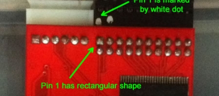
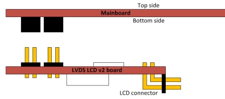
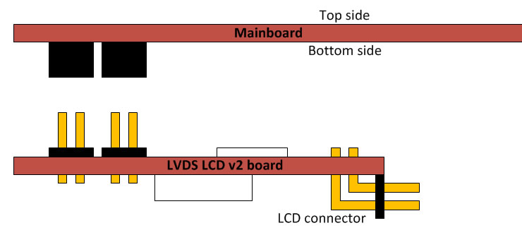
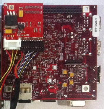
Connect LCD data and power connectors to LVDS PCB v2 like on drawing 1. Pin 1 is marked by white dot on data connector, and has rectangular shape on PCB. Power connector has key and can’t be inserted wrongly. Place PCB v2 to your mainboard. Please, pay attention that LCD and power connector on our PCB should be pointed toward center of motherboard (click drawing 2). You should get connection like on drawing 3 (BeagleBoard-xM is shown).

Missed shipments
I must ask for forgiveness because we missed to ship 16 orders placed to us in December. I wrote right before NY holidays that all orders have been shipped, but stupid mistake in our web-shop system made me fool. I’m really sorry about this! I know how eagerly you wait for your orders, and we will ship these missed orders by DHL to you this week.
The beginning of 2012 was really hard for us, we were not able to move to office because some office repair/renovation works were not finished in time, we had no Internet access for couple days, then we found this problem with un-programmed PIC controller (see my previous post), and now found mistake in our web-shop system that marked several orders as shipped. Lets hope that problems are over now, and we will come to normal work on this new web-site.
Problem with PIC firmware on first batch of PCB v2
Some of our first v2 PCB customers found that PIC doesn’t work normally, and LCD backlight flicks every 2-3 seconds. We made some internal investigations and found that around 30% of first batch of PIC microcontroller come to us with programmed code section, but not-programmed configuration section. As a result, watchdog timer on PIC was active (this is default option in PIC12F1840), and it reset PIC every 2-3 seconds that leads to flicks of LCD backlight. If you have such case, please proceed as follows:
-
If you have access to Microchip PicKit3 programmer, then please re-program HEX file to PIC controller (HEX-file is available together with sources in Support/Sources/PCBv2 section). The simplest way to re-program is to solder wires from PicKit right over the PIC in circuit (remove our PCB from motherboard). Here is connection diagram:
PicKit3 pin # PIC pin # 1 4 2 1 (or central pin of power IC) 3 8 (or pin 1 of power IC) 4 7 5 6 Here is command line for programming (supposed that hex file is in the C:\ root):
PK3CMD.exe -P12F1840 -E -M -Fc:\backlight_v1.hex -V3.3
- If you have no PicKit3 or have problems with re-programming, then please send us e-mail with Subject “PIC problem” and your Order ID inside e-mail body – we will ship correctly programmed PIC to you that you can solder on PCB.
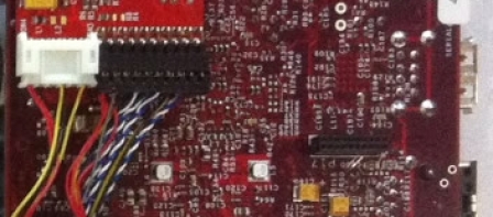
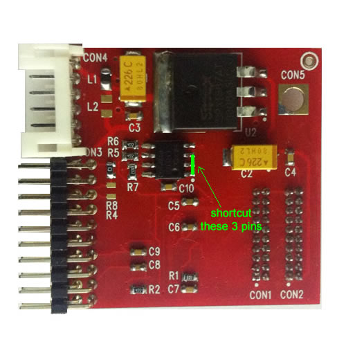
- Also, there is a simple workaround that will allow you to use LCD, but automatic brightness control will be disabled. Please, shortcut with wire pins 1, 2, and 3 of PIC like on attached photo (click on photo to enlarge it). This will force LCD backlight control pins to log.1 state and your LCD will work on max. brightness without any flicks.s
All new orders shipped since starting of this week come with correctly programmed PIC and do not require any changes. Now we do PIC programming internally in our company to avoid problems like this in the future.
We are back from holidays
We are back from holidays, and I will try to answer your 67 emails in 2-3 days.
Please, be patient! Thanks!
