Archive for Errata
Problem with artifacts on Pandaboard ES
UPDATED 3-Jul-2012 with more simple instruction, thanks to our customer Mark!
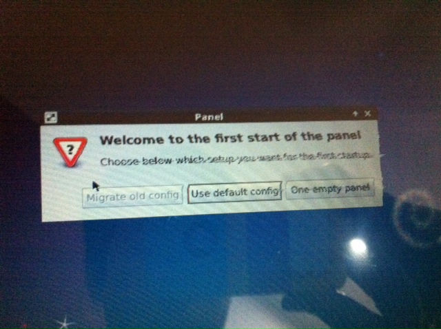
Some of our customers found that running our v2 board on Pandaboard ES gives some artifacts on LCD picture. You can notice on below photo that pixel rows are shifted on contrast areas (black text on white background).
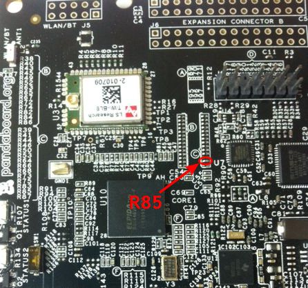
The same board has no artifacts running on Beagleboard, Beagleboard-xM, and original Pandaboard. To solve this problem you have to remove resistor R85 on PandaBoard-ES (second counting from the bottom in block C) and put 0 Ohm resistor or just put solder drop to short both pads.
That’s all, now artifacts should gone and you will have clear picture on Pandaboard ES.
Problem with PIC firmware on first batch of PCB v2
Some of our first v2 PCB customers found that PIC doesn’t work normally, and LCD backlight flicks every 2-3 seconds. We made some internal investigations and found that around 30% of first batch of PIC microcontroller come to us with programmed code section, but not-programmed configuration section. As a result, watchdog timer on PIC was active (this is default option in PIC12F1840), and it reset PIC every 2-3 seconds that leads to flicks of LCD backlight. If you have such case, please proceed as follows:
-
If you have access to Microchip PicKit3 programmer, then please re-program HEX file to PIC controller (HEX-file is available together with sources in Support/Sources/PCBv2 section). The simplest way to re-program is to solder wires from PicKit right over the PIC in circuit (remove our PCB from motherboard). Here is connection diagram:
PicKit3 pin # PIC pin # 1 4 2 1 (or central pin of power IC) 3 8 (or pin 1 of power IC) 4 7 5 6 Here is command line for programming (supposed that hex file is in the C:\ root):
PK3CMD.exe -P12F1840 -E -M -Fc:\backlight_v1.hex -V3.3
- If you have no PicKit3 or have problems with re-programming, then please send us e-mail with Subject “PIC problem” and your Order ID inside e-mail body – we will ship correctly programmed PIC to you that you can solder on PCB.
- Also, there is a simple workaround that will allow you to use LCD, but automatic brightness control will be disabled. Please, shortcut with wire pins 1, 2, and 3 of PIC like on attached photo (click on photo to enlarge it). This will force LCD backlight control pins to log.1 state and your LCD will work on max. brightness without any flicks.s
All new orders shipped since starting of this week come with correctly programmed PIC and do not require any changes. Now we do PIC programming internally in our company to avoid problems like this in the future.


