Our dualLVDS converter has two LVDS channels and supports 24-bits color panels with up to WUXGA (1920×1200 px) resolution. It also has on-board configurable backlight voltage generator and microcontroller with USB interface. We offer this converter as a standalone product, and also in bundle with 10″ WUXGA panel.
DualLVDS converter board has the following connectors:

Powering board
Converter board alone takes up to 0.4A current in active mode, with connected 10″ FullHD+ current goes up to 1.2A when backlight is set to maximum value. Board and LCD can be powered either by external power supply (5V at least 2A, jack is OD=2.6mm, ID=0.65mm, positive central pin) or by USB. By default it can be powered by external supply only. For USB power you should install 0R resistor in R12 position. CAUTION! Do not connect external power supply when R12 is installed, it can damage your USB port.
Backlight voltage generator
Converter has on-board configurable backlight voltage generator that can deliver up to 35V/1A. Backlight voltage can be set with R3, R11 resistors (see above picture for formula). We supply boards with default 24V backlight voltage. Take note that R11 should be in 5K – 20K range. If LCD backlight takes more than 3W, then U6 and L1 inductor can have temperature up to 100C degree. In this case you should use additional heat sink to avoid overheating.
LVDS cable
If you buy standalone board, then you will need to make your own LVDS cable for your LCD panel. We supply mate housing connector and 50 pcs of pin terminals together with board, they can be crimped to cable wires with AWG #32 crimp tool. We recommend using PA-09 crimp pliers, it has affordable price and provides high quality results. Below is pinout of LVDS connector, PDF version is available here: dualLVDS board pinout.
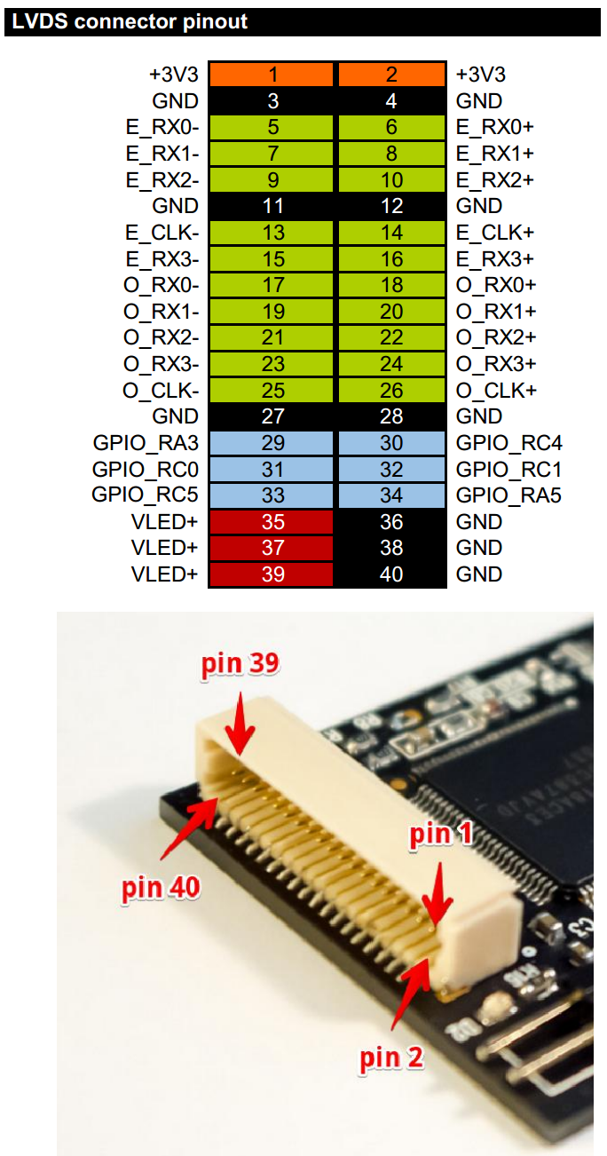
Pins GPIO_xxx are connected directly to PIC microcontroller and can be used to control different functions of LCD. We ship board with our standard example program (see source code below) that uses pin GPIO_RA5 to turn on LCD backlight when input video signal is detected. If video signal is lost, LCD backlight will be turned off. Also, pin GPIO_RC5 is connected to PIC PWM generator, and can be used to control brightness of LCD backlight.
Update of EDID information
We supply our converter board with pre-loaded EDID data for our 10″ FullHD+ LCD (resolution 1920×1200 px). You will need to update EDID information in converter in order to use it with your own LCD. EDID update procedure is described here: How to program custom EDID data in HDMI converter
Firmware update with USB bootloader
Board is supplied with embedded USB bootloader for easy firmware upload. To update firmware you should start board in bootloader mode by shorting both pins on ambient light sensor connector with jumper, then turn on power. Green LED will light on, and you will have 3 seconds to remove jumper in order to start bootloader. Green LED will blink when bootloader is active. You should follow steps 4 and 5 of this firmware upload procedure: Firmware upload HID USB bootloader is available here: HID USB bootloader. You can use firmware for our FullHD+ LCD bundle for your own LCD projects, latest version of firmware is available here: dualLVDS/FullHD+ firmware
Building PIC firmware
To build own PIC firmware you will need MPLAB.X environment from Microchip with XC8 compiler: MPLAB X, XC8 compiler.
Bootloader occupies the program memory region 0x000-0x903. The application firmware is supposed to occupy the 0x904-[end of flash] region of program memory.
Here are two linker setting changes that are required for the application project:
In addition to the above, make certain that all configuration bit settings between the bootloader firmware project, and the application firmware project, match 100% exactly, see our example firmware for details:
1 2 3 4 5 6 7 8 9 10 11 12 13 14 15 16 17 18 19 20 21 22 23 24 25 26 27 28 29 30 31 32 | #include "typedefs.h" __CONFIG(FOSC_INTOSC & WDTE_OFF & PWRTE_ON & MCLRE_OFF & CP_OFF & BOREN_ON & CLKOUTEN_OFF & IESO_OFF & FCMEN_OFF); __CONFIG(WRT_OFF & CPUDIV_NOCLKDIV & USBLSCLK_48MHz & PLLMULT_3x & PLLEN_ENABLED & STVREN_ON & BORV_LO & LPBOR_OFF & LVP_OFF); #define _XTAL_FREQ 48000000 // Frequency of crystal (INTOSC in our case) void main(void) { OSCCON = 0xFC; // 3x PLL enabled from 16MHz HFINTOSC ACTCON = 0x90; // Enable active clock tuning from USB while(OSCSTATbits.PLLRDY == 0); // Wait for PLL ready/locked ANSELAbits.ANSA4=0; TRISAbits.TRISA4=1; // Define SCDT In pin (input) LATAbits.LATA5=0; TRISAbits.TRISA5=0; // Define SCDT Out pin (output, default to 0) LATCbits.LATC5=0; TRISCbits.TRISC5=0; // Define PWM pin (output, default to 0) LATCbits.LATC3=1; TRISCbits.TRISC3=0; // Define LED pin (output, default to 1 - LED Off) while(1) { // If video signal is detected if (PORTAbits.RA4) { LATAbits.LATA5=1; // Enable video outputs LATCbits.LATC5=1; // Enable backlight (PWM=1 - max. brightness) LATCbits.LATC3=0; // Turn LED On } // If video signal is lost else { LATAbits.LATA5=0; // Disable video outputs LATCbits.LATC5=0; // Disable backlight (PWM=0 - turn off backlight) LATCbits.LATC3=1; // Turn LED Off } } } |
Ambient light sensor and backlight brightness
Ambient light sensor is available as an option, and can measure ambient light level for automatic backlight control.

Ambient light sensor should be connected to connector J1, red color wire to pin 1 on connector. Light level is available as a voltage in range 0 (dark) to 2.5V (max. light) on pin RC2 (ADC channel 6) of PIC microcontroller. Backlight brightness can be controlled with help of PWM signal on GPIO_RC5. Additional information about backlight control through USB HID commands is available in this how-to: How to control LCD backlight (USB HID)
Board schematic
Board schematic is available here: http://goo.gl/NSWTIQ
See in action
Video with dualLVDS converter board and our FullHD+ LCD is available here: FullHD+ LCD with HDMI dualLVDS converter
Follow us on Twitter to get instant notification about new firmware release: Follow @ChalkElec


© 2011-2023 Chalkboard Electronics ® All rights reserved.
Can you set the backlight voltage of dual LVDS converter with 12V?
If there was a way, let me know how.
Yes, you can, read carefully “Backlight voltage generator” part of this How-to.
can you provide part number and manufacturer of the LVDS connector installed on PCB of HDMI to Dual LVDS converter.
I have bought the HDMI to LVDS converter. I need to make more LVDS cables.
Please reply As soon as possible.
1. Board connector: https://www.digikey.com/product-detail/en/jst-sales-america-inc/SM40B-SRDS-G-TF(LF)(SN)/455-1868-2-ND/926774
2. Wire housing: https://www.digikey.com/product-detail/en/jst-sales-america-inc/SHDR-40V-S-B/455-1438-ND/759927
3. Wire pins: https://www.digikey.com/product-detail/en/jst-sales-america-inc/SSH-003T-P0.2/455-1561-1-ND/720818
Can this also drive lower resolution LCDs using only 4 of the lvds wire pairs?
Yes, it has resistor to switch between dual-LVDS and single-LVDS modes