Archive for How-To
How to build kernel for Beaglebone for custom cape support
In this How-to we will try to build kernel for Beaglebone that will support our LVDS cape.
Download and install all required sources:
sudo apt-get install gcc-arm-linux-gnueabi git ccache libncurses5-dev u-boot-tools lzma
cd ~
git clone git://git.kernel.org/pub/scm/linux/kernel/git/stable/linux-stable.git
git clone git://github.com/RobertCNelson/linux-dev.git
cd linux-dev
git checkout origin/am33x-v3.2 -b am33x-v3.2
cp system.sh.sample system.sh
Then make the following changes in system.sh:
– uncomment line CC=arm-linux-gnueabi-
– uncomment line LINUX_GIT=~/linux-stable/
– uncomment line ZRELADDR=0x80008000
– uncomment line BUILD_UIMAGE=1
– uncomment and change line MMC=/dev/sde to your SD card system name (mine is /dev/sdb)
Next commands:
./build_kernel.sh
will bring you directly to kernel config GUI, and then will assemble it.
After kernel is compiled, please make changes to file ~/linux-dev/KERNEL/arch/arm/mach-omap2/board-am335xevm.c (see below), then recompile kernel again (command “tools/rebuild.sh”). Once the build had completed there will be a uImage file in ~/linux-dev/deploy. You can install this to your SD card with:
./tools/load_uImage.sh
Built kernel modules are located in ~/linux-dev/deploy/mod/lib
To add support for our LVDS cape you need to patch file board-am335xevm.c located in /kernel/arch/arm/mach-omap2. You should find function beaglebone_cape_setup(struct
memory_accessor *mem_acc, void *context) in this file and change it to always invoke function dvi_init(0,0). The easiest way is to put
the following lines:
pr_info("BeagleBone cape: initializing DVI cape\n");
dvi_init(0,0);
return;
at the beginning of function.
How to get touchscreen working
Some Linux distros come with these drivers included in kernel, others not. If you can’t use touchscreen after Linux is running in X GUI mode or if you don’t have assigned input device in console mode, then you should do the following:
- First of all, check all connections. We had many cases when customers forgot or incorrectly connected touchscreen to miniUSB add-on board.
- Connect just touchscreen through USB cable to normal PC running Windows. If touchscreen is detected and you can use it in Windows, then all connections are OK and you can proceed further.
- If your Linux kernel does not include drivers for touchscreen, then you should recompile kernel with the following options:
- for AUO LCD (1024×600 px): “Device Drivers –> HID Devices –> Special HID drivers –> HID Multitouch panels“, option name: CONFIG_HID_MULTITOUCH, available in mainline kernel since version 2.6.38
- for LG LCD (1280×800 px, black frame): “Device Drivers –> HID Devices –> Special HID drivers –> N-Trig touchscreens“, option name: CONFIG_HID_NTRIG, available in mainline kernel since version 2.6.31
- If you run Android, then you can encounter problem with non-correct touchscreen vs screen resolution. This happen because Android supposes default screen resolution for external LCD as 720p or 1080p (touchscreen is connected by USB and is considered as external device), but our LCD is 1024×600 or 1280×800. You can easy check it by simply turning on option “Show touches” in Settings->Developer options of Android. Then you will notice the difference in real position of touch and Android touch position. This can be easy improved by placing one of below files to /system/usr/idc folder of Android rootfs. After that touchscreen size and LCD size will match.
File for Ntrig touchscreen (1280×800, black frame)
File for Cando touchscreen (1024×600)
See below links for additional information on touchscreen devices functionality under Android:
Touch devices in Android
Input device configuration files - You can use console command getevent (sources for Linux are here: getevent.zip) to check what touchscreen returns when you touch it. Also, you can get more details about touchscreen and its modes with commands getevent -p and getevent -i.
- N-trig touchscreen can be tuned with some parameters:
- min_width – minimum touch contact width to accept
- min_height – minimum touch contact height to accept
- activate_slack – number of touch frames to ignore at the start of touch input
- deactivate_slack – number of empty frames to ignore before deactivating touch
- activation_width – width threshold to immediately start processing touch events
- activation_height – height threshold to immediately start processing touch events
They can be changed right from console, see here for details: http://baruch.siach.name/blog/posts/linux_kernel_module_parameters/
- If you have problems with touchscreen, like “crazy” cursor jumps or “phantom” mouse clicks, then try to follow this guide How to calibrate N-Trig touchscreen
- Still no success? Drop e-mail to support@chalk-elec.com and provide description of problem + photo of your LCD touch connection + output of commands “lsusb” and “dmesg” entered in Linux console.
How to connect RaspberryPi to LCD and have fun
You will need:
1. LCD panel
2. LVDS cable with attached miniUSB connector (for touch controller) and ambient light sensor
3. HDMI-LVDS converter
4. miniUSB cable – optionally available during order
5. Power adapter (5V, at least 2A) – optionally available during order

All above you will receive with our LCD bundle order.
Also, you will need additionally:
6. SD card
7. microUSB cable to power RasPi
8. RaspberryPi board itself

Here are the steps to get LCD working:
1. Download latest image of Raspbian from www.raspbian.org or www.raspberrypi.org. I used version “2012-09-18-wheezy-raspbian” for demo.
2. Create SD card based on this image.
3. – if you have 10″ LG panel and your HDMI board has U5 chip installed, then skip to p.4
– if you have 7″ CPT panel with resistive touchscreen, then download this config.txt file and put it to the root of boot partition of SD card
– if you have old HDMI board and 10″ LG panel, then open file called “config.txt” on just created SD card and add single line at the top: “hdmi_edid_file=1″, then download file edid.dat and copy it to the root of boot partition of SD card
– if you have your own LCD, then you should create binary EDID file (full file name edid.dat) yourself following datasheet of your LCD and copy this “edid.dat” file to the root of boot partition of SD card
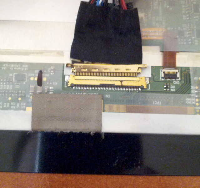
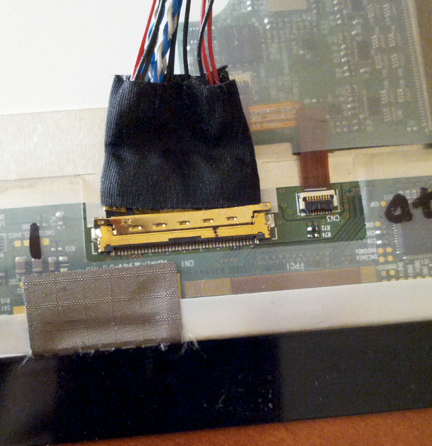
4. Connect LVDS cable to LCD as on below photos. Cable connector should be fully inserted into mate connector on backside of LCD.
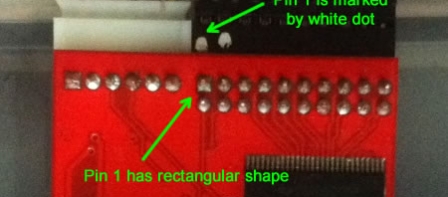
5. Connect LVDS cable to HDMI-LVDS board as on below photo. Pin 1 of cable is marked with white dot.
6. Connect microUSB cable from HDMI-LVDS board to RasPi microUSB connector.

7. Connect miniUSB cable between RasPi USB port and small red board that is part of LVDS cable.

8. Connect cable of power adapter to HDMI-LVDS board.

9. Turn on power, this will start your RaspberryPi and you should get image on screen immediately. During first run Raspbian will run configuration utility. Touchscreen is not working at yet, and you will need usual USB keyboard to enable option “Start desktop on boot”.

10. After RasPi will restart to GUI, you will be able to use touchscreen as a mouse.

Final SD card image for 10″ LCD (at least 4Gb card) is here: SD card test image
We use this SD card image to test our bundles before shipping.
Some of our first customers (who placed order in September) can encounter problems with LCD backlight. If you see that backlight is not turned on when you apply power to our HDMI-LVDS board (screen is completely black, no light from the side view of LCD), then you has 2 ways to improve this:
1. Short pins 1 and 3 on white 6-pins connector (CON4). Pin 1 has square shape, others pins have round shape. Don’t worry if you short pin 2 as well – it is not connected anywhere.
or
2. Short pins 1,2,3 on PIC microcontroller (U3). Pin 1 is marked with white dot. Don’t worry if you short pin 4 as well – it anyway tied up to power.

UPDATE: here is interesting post from one of our customers about his experience with connection of our 10″ LCD Raspberry Kiosk
How to install and configure Debian/Ubuntu on Beagleboard (xM), BeagleBone, and Pandaboard (ES)
Below is the simplest instruction of installing and configuring Debian/Ubuntu with LCD support.
- Go to https://github.com/RobertCNelson/netinstall, select required distro and proceed with mk_mmc.sh script. It will automatically download required files and configure minimal working system on your SD card.
-
Then, go to “boot” partition of your SD card, find file “uEnv.txt” and change parameter “dvimode” for 10″ AUO LCD (1024×600) and 7″ CPT LCD (1024×600, resistive touch):
"dvimode=1024x600MR-16@60"
or for 10″ LG LCD (1280×800, black frame) and new gen 7″ panels (1280×800, capacitive touch):
"dvimode=1280x800MR-16@60"
How to compile Android ICS with touchscreen support
This post was created with valuable help of Zhi Yong Woo and Benjamin Tissoires
OK, lets make our own Android ICS tablet based on PandaBoard and our 10″ LCD bundle. We will use Linaro 12.01 build.
Prerequisites
We will need Ubuntu 11.04 x64 as a host machine. I tried different others hosts including 10.04LTS and 11.10, but only 11.04 x64 gave me working result. You can install your machine in VirtualBox – that’s exactly what I did. Just turn on Intel virtualization (VT-x) option in BIOS an enable it in VirtualBox. Also, you will need around 40 Gbytes of free disk space.
Install required packages
sudo apt-get install git-core gnupg flex bison gperf build-essential \
        zip curl zlib1g-dev libc6-dev lib32ncurses5-dev ia32-libs \
        x11proto-core-dev libx11-dev lib32readline5-dev lib32z-dev \
        libgl1-mesa-dev g++-multilib mingw32 tofrodos python-markdown \
        libxml2-utils xsltproc libncurses5-dev libreadline6-dev \
        gcc-arm-linux-gnueabi uboot-mkimage
Install Java JDK
Oracle forced to remove Java JDK from standard Ubuntu repository recently. Therefore, we will use small trick to install JDK.
wget https://raw.github.com/flexiondotorg/oab-java6/master/oab-java6.sh -O oab-java6.sh
chmod +x oab-java6.sh
sudo ./oab-java6.sh
sudo apt-get install sun-java6-jdk
Install Linaro image tools
sudo add-apt-repository ppa:linaro-maintainers/tools
sudo apt-get update
sudo apt-get install linaro-image-tools
Install Repo tool
curl https://dl-ssl.google.com/dl/googlesource/git-repo/repo > ~/bin/repo
export PATH=$HOME/bin:$PATH
chmod a+x ~/bin/repo
Download Android source code (Linaro 12.01)
export MANIFEST_REPO=git://android.git.linaro.org/platform/manifest.git
export MANIFEST_BRANCH=linaro_android_4.0.3
export MANIFEST_FILENAME=landing-panda.xml
mkdir ~/work
mkdir ~/work/android
cd ~/work/android
repo init -u ${MANIFEST_REPO} -b ${MANIFEST_BRANCH} -m ${MANIFEST_FILENAME}
repo sync
This will download > 2 Gb of sources and will take around one hour (highly depends on your Internet speed).
Download toolchain
cd ~/work
wget --no-check-certificate http://releases.linaro.org/12.01/components/android/toolchain/4.6/android-toolchain-eabi-linaro-4.6-2012.01-2-2012-01-13_19-04-18-linux-x86.tar.bz2
tar -jxvf android-toolchain-eabi-linaro-4.6-2012.01-2-2012-01-13_19-04-18-linux-x86.tar.bz2
Build source code
cd ~/work/android
export TARGET_PRODUCT=pandaboard
export TARGET_SIMULATOR=false
export TARGET_TOOLS_PREFIX=~/work/android-toolchain-eabi/bin/arm-linux-androideabi-
make TARGET_PRODUCT=${TARGET_PRODUCT} TARGET_TOOLS_PREFIX=${TARGET_TOOLS_PREFIX} HOST_CC=gcc-4.5 HOST_CXX=g++-4.5 HOST_CPP=cpp-4.5 boottarball systemtarball userdatatarball
If you have multi-core processor, then you should try to use “make -jX …” to speed-up compilation. I used “make -j8 …” on my i7 processor. Compilation time highly depends on your computer and can vary from 20 minutes to several hours. So, have another cup of coffee and keep fingers crossed 🙂
Build source code
cd ~/work/android
export TARGET_PRODUCT=pandaboard
export TARGET_SIMULATOR=false
export TARGET_TOOLS_PREFIX=~/work/android-toolchain-eabi/bin/arm-linux-androideabi-
make TARGET_PRODUCT=${TARGET_PRODUCT} TARGET_TOOLS_PREFIX=${TARGET_TOOLS_PREFIX} HOST_CC=gcc-4.5 HOST_CXX=g++-4.5 HOST_CPP=cpp-4.5 boottarball systemtarball userdatatarball
If you have multi-core processor, then you should try to use “make -jX …” to speed-up compilation. I used “make -j8 …” on my i7 processor. Compilation time highly depends on your computer and can vary from 20 minutes to several hours.
Find out the name of your SD card device
Insert SD card and enter the following command:
df -h
You will see the list of storage devices, you should find out which one is your SD card. Mine has name “sdb”, and I will use it in the next command.
Install Android image to SD card
cd ~/work/android/out/target/product/pandaboard
sudo linaro-android-media-create --mmc /dev/sdb --dev panda --system system.tar.bz2 --boot boot.tar.bz2 --userdata userdata.tar.bz2
sync
We use here “sdb” as a name of SD card. Now remove SD card and insert it again – you will see several partitions opened in separate windows.
Apply Android binary patch
Insert SD card and enter the following command:
cd ~/work
wget http://releases.linaro.org/12.01/android/images/landing-panda/install-binaries.sh
chmod a+x install-binaries.sh
./install-binaries.sh /dev/sdb2
sync
Here we again use “sdb” as a name of SD card (2 is added to point to system partition).
Set correct LCD resolution
Go to “/media/boot” folder (this is boot partition of your SD card), open file “boot.txt” and add the following arguments to “setenv bootargs …” string:
omapfb.mode=dvi:1024x600MR-24@60 consoleblank=0
Now save file. And enter the following command to generate boot script:
sudo mkimage -A arm -O linux -T script -C none -a 0 -e 0 -n 'boot script' -d boot.txt boot.scr
sync
Now we have working Android with correct LCD output, but our touchscreen doesn’t work. Well, that’s right time to recompile kernel to add touchscreen support. Lets’ proceed!
Configure kernel
cd ~work/android/kernel
make ARCH=arm CROSS_COMPILE=arm-linux-gnueabi- panda_defconfig
make ARCH=arm menuconfig
Now select this driver in configuration menu:
Device Drivers --> HID Devices --> Special HID drivers --> HID Multitouch panels
Save configuration and exit.
Build kernel and copy to boot partition on SD card
make ARCH=arm CROSS_COMPILE=arm-linux-gnueabi- uImage
cp ~work/android/kernel/arch/arm/boot/uImage /media/boot
sync
Now we have working touchscreen, but it works really weird – only left top corner is working as projected to whole screen. This is because Android gets HDMI default resolution (1920×1080) and assigns it to touchscreen. Our touchscreen is connected through USB and is considered as “external” device, so Android thinks it is related to HDMI input. Therefore we have to configure touchscreen to be considered as “internal” device (just set parameter . Then Android will assign DVI resolution to it.
Configure touchscreen resolution
- Connect Pandaboard to PC with mini-USB cable and run ADB utility (it is available in Android SDK)
- Get file from this link Vendor_2087_Product_0a01.idc and put it to your current folder
- Enter the following commands to remount Android file system in R/W mode and to copy configuration file:
adb remount
adb push Vendor_2087_Product_0a01.idc /system/usr/idc/Vendor_2087_Product_0a01.idc
adb sync
- Restart Pandaboard
- You should have fully working touchscreen now.
Here are links to built images, kernel and boot.scr file:
boot.tar.bz2
system.tar.bz2
userdata.tar.bz2
boot.scr
Kernel
Full SD card image (use DD or Win32DiskImage to write to card)
How to setup correct LCD resolution
Most of modern LCD panels have embedded EEPROM memory with I2C interface that stores important information about its capabilities (including LCD resolution). This data usually takes 128 bytes and is referred as Extended Display Identification Data (EDID). Linux kernel searches for available EEPROM memories during startup and read this data.
Our v2 PCB uses a little bit different approach. It does not provide direct access from baseboard to LCD EDID info. Instead of this, it has PIC controller with embedded EEPROM, that can be programmed with EDID information and will pretend to baseboard to be LCD EDID EEPROM. This was done for three main reasons:
- Baseboard (BeagleBoard/PandaBoard) uses 1.8V level for I2C bus, but LCD requires 3.3V. So, we saved couple bucks on level translator (and you saved as well :).
- We get LVDS cables from LCD supplier without these 4 lines for EDID access. This is normal situation for LCDs that are supplied for notebooks. Making custom LVDS cable would increase the final price of our bundle.
- Some displays have different modes of operation with different resolution. And you can easy program different EDID data to PIC controller and switch between them during start-up.
Our current PIC firmware (version 1.0) does not include EDID procedure. New version with EDID support will be published soon. Therefore, below is short guide on manual changing of LCD resolution for Ubuntu and Android.
Linux kernel allows to assign manual LCD resolution in bootargs supplied by u-boot. This is usually done by script called “boot.scr” in “boot” partition that is loaded and executed by u-boot. “boot.scr” has special format and usually is created with the help of “mkimage” util from source file called “boot.txt”. Below is example of my “boot.txt” that I use for Android (Linaro build 12.01):
setenv initrd_high "0xffffffff"
setenv fdt_high "0xffffffff"
setenv bootcmd "fatload mmc 0:1 0x80200000 uImage; fatload mmc 0:1 0x81600000 uInitrd; bootm 0x80200000 0x81600000"
setenv bootargs "console=ttyO2,115200n8 rootwait ro earlyprintk fixrtc nocompcache vram=48M omapfb.vram=0:24M,1:24M omapfb.video_mode=1024x600MR-16@60 mem=456M@0x80000000 mem=512M@0xA0000000 init=/init androidboot.console=ttyO2"
boot
and for Ubuntu:
fatload mmc 0:1 0x80000000 uImage
fatload mmc 0:1 0x81600000 uInitrd
setenv bootargs ro elevator=noop vram=12M omapfb.mode=dvi:1024x600MR-16@60
bootm 0x80000000 0x81600000
You should consider above “boot.txt” files as examples only, because they highly depend on OS and baseboard that you use.
The most important bootarg here is “omapfb.video_mode=1024x600MR-16@60” – that’s exactly where we setup LCD resolution. 1024×600 sets resolution, “M” indicates the kernel will calculate a VESA mode on-the-fly instead of using modedb look-up, the “R” indicates reduced blanking which is for LCD panels, “16” is the color depth, “@60” is the # of frames per second.
Lets generate “boot.scr” file with the following commands:
mkimage -A arm -O linux -T script -C none -a 0 -e 0 -n "Run uImage" -d boot.txt boot.scr
chmod a+x boot.scr
“mkimage” is available in package “uboot-mkimage”.
Now copy generate “boot.scr” file to boot partition on your SD card, unmount it, put into baseboard and try. You should have native 1024×600 resolution now.
How to control LCD backlight brightness
Brightness level in LCD panels is controlled by pulse-width modulation (PWM). PWM is a simple turning the switch between supply and load on and off at a fast rate. The longer the switch is on compared to the off periods, the higher the power supplied to the load is. The PWM switching frequency has to be much faster than what would affect the load, which is to say the device that uses the power. Typically, switching frequency is set to about 200 Hz in most LCD backlight control units.
The term duty cycle describes the proportion of time when switch is on to the regular period of time. A low duty cycle corresponds to low power (low brightness in our case), because the power is off for most of the time. Duty cycle is expressed in percent, 100% being fully on (max. backlight brightness).
Below are several examples of different duty cycles. That’s exactly the waveforms that you can see with oscilloscope connected to pin 4 of connector CON4 on our v2 PCB.

PWM waveform is generated by PIC12 microcontroller (U3) on our PCB. The duty cycles of PWM depends on voltage measured on its pin 7 (AN0) that is used as an input to internal analog to digital converter (ADC). We supply our LCD bundle with ambient light sensor connected to this pin. PIC12 measures voltage 10 times every second, and smoothly changes PWM duty cycle. Full cycle of brightness change takes 2 seconds to avoid screen flickers. Here is short video that shows how this works.
For manual brightness change you can substitute ambient light sensor with 10K variable resistor.
Now you can turn knob to control brightness of screen. Please, be aware that it has the same delay of 2 seconds to change brightness to new level. And finally, short video of manual brightness control in action.
Also, you can increase default brightness level by adding resistor in parallel with light sensor. The lower value of resistor will provide higher default brightness level.
How to connect our PCB v2
First of all, please follow below instructions to make required modifications to your mainboard (click on your mainboard name near “+” to get additional details).
BeagleBoard
BeagleBoard-xM
PandaBoard
PandaBoard-ES
Our LVDS PCB is connected through two Parallel LCD Expansion Headers on the bottom side of mainboard. They are:
- J4 and J5 for BeagleBoard
- P11 and P13 for BeagleBoard-xM
- J1 and J4 for PandaBoard
- J1 and J4 for PandaBoard-ES
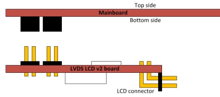
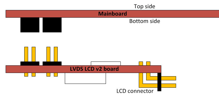
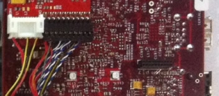
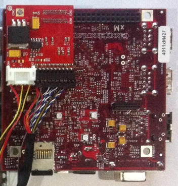
Connect LCD data and power connectors to LVDS PCB v2 like on drawing 1. Pin 1 is marked by white dot on data connector, and has rectangular shape on PCB. Power connector has key and can’t be inserted wrongly. Place PCB v2 to your mainboard. Please, pay attention that LCD and power connector on our PCB should be pointed toward center of motherboard (click drawing 2). You should get connection like on drawing 3 (BeagleBoard-xM is shown).