Prerequisites
For first startup you will need:
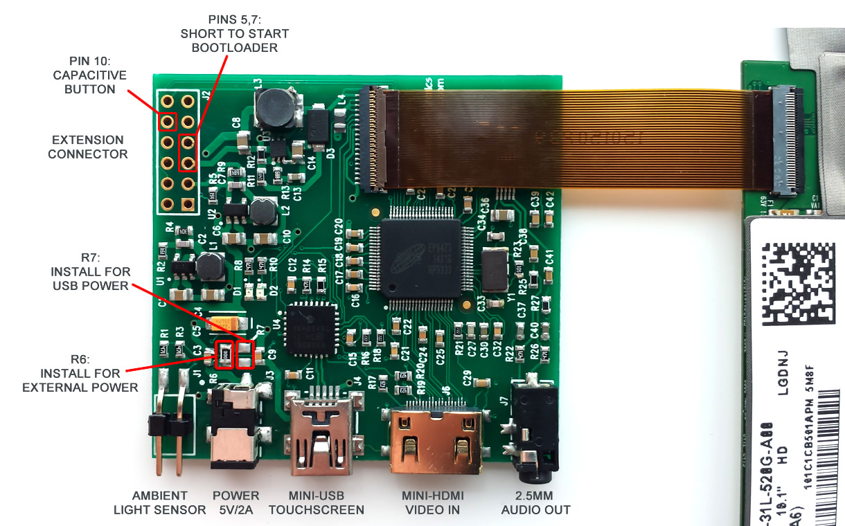
LCD control board is fixed on the back side of LCD and connected to LCD panel by FPC cable:
Powering LCD
LCD with control electronics takes around 1.2A current when backlight is set to maximum value, and it can be powered either by external power supply (5V/2A, jack is OD=2.6mm, ID=0.65mm, positive central pin) or by USB. Power mode is selected by installing one of 0R resistor – R6 for normal power supply or R7 for USB power. CAUTION! Do not install both resistors at once, because this can damage USB port on your computer.
By default we supply LCD with R6 installed, therefore you will need external power supply to run LCD. For USB power you should change 0R resistor from R6 position to R7 position, and make sure that your USB port can continuously provide at least 1.2A current. Power consumption can be significantly decreased by lowering backlight level.
Firmware upgrade
We constantly add new features and provide bug fixes by releasing new firmware for our LCD panels. To update firmware you should start LCD in bootloader mode by shorting pins 5 and 7 on extension header before switching on power, then follow this firmware upload procedure: https://www.chalk-elec.com/?p=1826
New firmware for this 10″ panel is available here: http://goo.gl/wg8WY5
Follow us on Twitter to get instant notification about new firmware release: Follow @ChalkElec
Capacitive touchscreen
LCD touchscreen is based on capacitive technology with up to 10 fingers support, and can work in two modes depending on programmed firmware: single-touch mode and multi-touch mode. We supply LCD with default single-touch mode, because it can work without drivers with any USB host. For multi-touch mode you will need to follow firmware upgrade procedure described above and update Linux/Android kernel as per this How-to: https://www.chalk-elec.com/?p=2028
Ambient light sensor and backlight control
Starting from version 2.0 firmware for our 10″ integrated LCD supports LCD backlight control through standard USB HID protocol and automatic backlight control with optional ambient light sensor. Ambient light sensor should be connected to connector J1, red color wire to pin 1 on connector (pin 1 is marked with white dot). Additional details about backlight control from your host board or PC through USB HID commands are available here: How to control LCD backlight (USB HID).
Capacitive button
To be added.


© 2011-2023 Chalkboard Electronics ® All rights reserved.
[…] the touchscreen through Raspberry Pi’s USB. To change the power source, you can look up this link. You need to de-solder and solder to change the power source of this Touchscreen. So if you […]