Our blog
How to control LCD backlight (USB HID)
Starting from version 2.0 all firmwares for our LCD and HDMI converters support LCD backlight control through standard USB HID protocol.
HID report descriptor
The following HID report descriptor is used:
1 2 3 4 5 6 7 8 9 10 11 12 13 14 15 16 17 18 19 20 21 22 23 | 0x05, 0x0C, // Usage Page (Consumer) 0x09, 0x01, // Usage (Consumer Control) 0xA1, 0x01, // Collection (Application) 0x15, 0x00, // Logical Minimum (0) 0x25, 0x01, // Logical Maximum (1) 0x75, 0x01, // Report Size (1) 0x95, 0x07, // Report Count (7) 0x19, 0x6F, // Usage Minimim (0x6F) 0x29, 0x75, // Usage Maximum (0x75) 0x91, 0x02, // * Output (Data, Var, Abs) 0x95, 0x01, // Report Count (1) 0x91, 0x03, // * Output (Const, Var, Abs) 0x25, 0x23, // Logical Maximum (35) 0x75, 0x08, // Report Size (8) 0x09, 0x71, // Usage (0x71 - Display Brightness) 0x91, 0x02, // * Output (Data, Var, Abs) 0x09, 0x35, // Usage (0x35 - Illumination) 0x26, 0xFF, 0x00, // Logical Maximum (255) 0x81, 0x02, // ** Input (Data, Var, Abs) 0x05, 0x20, // Usage Page (Sensors) 0x09, 0x41, // Usage (0x41 - Ambient Light Sensor) 0x81, 0x02, // ** Input (Data, Var, Abs) 0xC0 // End Collection |
Report usages follow recent changes in official USB HID specification proposed by Microsoft in change request #HUTRR41. Interface # is 0 for HDMI-dualLVDS converter and FullHD+ LCD bundle, Interface # is 1 for open frame/black frame 7″ LCD and for new 10″ integrated LCD. Report ID is 0 for all cases.
Packet format
Firmware accepts 2-bytes packet request from host and reply with 2-bytes packet with information about current backlight mode and ambient light level:

Only one bit can be active in command byte of request packet. If bit 5 is active (Set Brightness command), then next byte contains desired brightness level. For others commands second byte is ignored. LCD will reply with current backlight status and ambient light sensor value to any received command. To get current status without performing command you can send request with command byte equal to 0. MAX_BL is 35 for HDMI-dualLVDS converter and FullHD+ LCD bundle, MAX_BL is 18 for open frame/black frame 7″ LCD and for new 10″ integrated LCD.
How to send commands
The simplest way to communicate with HID devices is to to use cross-platform library HIDAPI from Signal11. With HIDAPI it is just several lines of code to control LCD brightness:
1 2 3 4 5 6 7 8 9 10 11 12 13 14 15 16 17 18 19 20 21 22 23 24 25 26 27 28 29 30 31 32 33 34 35 36 37 38 39 40 41 42 43 44 45 46 47 48 49 50 51 52 53 54 55 56 57 58 59 60 61 62 63 64 65 66 67 68 69 70 71 72 73 74 | #include <stdio.h> #include "hidapi.h" // Try to open HID device and return pointer to opened device hid_device* openHID() { struct hid_device_info *devs, *cur_dev; hid_device* device = NULL; int iface = 1; // We use interface# 1 for 7" and 10", and interface# 0 for dualLVDS/FullHD+ // VID=0x04D8, PID=0xF724 for 7" and 10" multi-touch firmware, interface# is 1 // VID=0x04D8, PID=0xF723 for 7" and 10" single-touch firmware, interface# is 1 // VID=0x04D8, PID=0x003F for dualLVDS/FullHD+, interface# is 1 devs = hid_enumerate(0x04D8, 0xF724); if (devs == NULL) { devs = hid_enumerate(0x04D8, 0xF723); if (devs == NULL) { devs = hid_enumerate(0x04D8, 0x003F); if (devs == NULL) return NULL; else iface = 0; } } // Walk through all enumerated devices to find one with correct interface number cur_dev = devs; while (cur_dev) { if ((cur_dev->interface_number) == iface) { device = hid_open_path(cur_dev->path); printf("Found Backlight interface at path: %s", cur_dev->path); break; } cur_dev = cur_dev->next; } hid_free_enumeration(devs); return device; } int main(int argc, char *argv[]) { hid_device* device=NULL; unsigned char buf[3]; buf[0] = 0x0; // Report ID (0) buf[1] = 0x04; // Command (0x20 - Set Backlight) buf[2] = 9; // Backlight value for command Set Backlight hid_init(); device = openHID(); if (device == NULL) { puts("Can't find USB device with interface for backlight"); return -1; } hid_set_nonblocking(device, true); printf("Writing bytes: %02X,%02X,%02X\n", buf[0], buf[1], buf[2]); if (hid_write(device, buf, 3) == -1) { puts("Error writing bytes to device!"); hid_close(device); return -1; } if (hid_read_timeout(device, buf, 2, 100) == -1) { puts("Error reading bytes to device!"); hid_close(device); return -1; } printf("Received bytes: %02X,%02X\n", buf[0], buf[1]); return 0; } |
Above example is universal and will work with all our products with USB backlight control feature.
GUI application for LCD control
Cross-platform GUI application to control different LCD settings including brightness is available here:
LCD control GUI
You will need Qt framework to build it from sources.
See in action
Video with backlight test using our dualLVDS converter FullHD+ LCD is available here: Backlight test video
Follow us on Twitter to get instant notification about updates: Follow @ChalkElech
How to use HDMI-dualLVDS converter
Our dualLVDS converter has two LVDS channels and supports 24-bits color panels with up to WUXGA (1920×1200 px) resolution. It also has on-board configurable backlight voltage generator and microcontroller with USB interface. We offer this converter as a standalone product, and also in bundle with 10″ WUXGA panel.
DualLVDS converter board has the following connectors:

Powering board
Converter board alone takes up to 0.4A current in active mode, with connected 10″ FullHD+ current goes up to 1.2A when backlight is set to maximum value. Board and LCD can be powered either by external power supply (5V at least 2A, jack is OD=2.6mm, ID=0.65mm, positive central pin) or by USB. By default it can be powered by external supply only. For USB power you should install 0R resistor in R12 position. CAUTION! Do not connect external power supply when R12 is installed, it can damage your USB port.
Backlight voltage generator
Converter has on-board configurable backlight voltage generator that can deliver up to 35V/1A. Backlight voltage can be set with R3, R11 resistors (see above picture for formula). We supply boards with default 24V backlight voltage. Take note that R11 should be in 5K – 20K range. If LCD backlight takes more than 3W, then U6 and L1 inductor can have temperature up to 100C degree. In this case you should use additional heat sink to avoid overheating.
LVDS cable
If you buy standalone board, then you will need to make your own LVDS cable for your LCD panel. We supply mate housing connector and 50 pcs of pin terminals together with board, they can be crimped to cable wires with AWG #32 crimp tool. We recommend using PA-09 crimp pliers, it has affordable price and provides high quality results. Below is pinout of LVDS connector, PDF version is available here: dualLVDS board pinout.
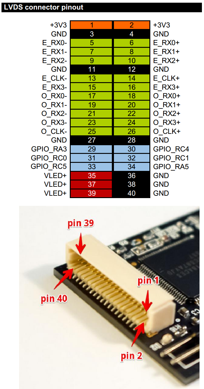
Pins GPIO_xxx are connected directly to PIC microcontroller and can be used to control different functions of LCD. We ship board with our standard example program (see source code below) that uses pin GPIO_RA5 to turn on LCD backlight when input video signal is detected. If video signal is lost, LCD backlight will be turned off. Also, pin GPIO_RC5 is connected to PIC PWM generator, and can be used to control brightness of LCD backlight.
Update of EDID information
We supply our converter board with pre-loaded EDID data for our 10″ FullHD+ LCD (resolution 1920×1200 px). You will need to update EDID information in converter in order to use it with your own LCD. EDID update procedure is described here: How to program custom EDID data in HDMI converter
Firmware update with USB bootloader
Board is supplied with embedded USB bootloader for easy firmware upload. To update firmware you should start board in bootloader mode by shorting both pins on ambient light sensor connector with jumper, then turn on power. Green LED will light on, and you will have 3 seconds to remove jumper in order to start bootloader. Green LED will blink when bootloader is active. You should follow steps 4 and 5 of this firmware upload procedure: Firmware upload HID USB bootloader is available here: HID USB bootloader. You can use firmware for our FullHD+ LCD bundle for your own LCD projects, latest version of firmware is available here: dualLVDS/FullHD+ firmware
Building PIC firmware
To build own PIC firmware you will need MPLAB.X environment from Microchip with XC8 compiler: MPLAB X, XC8 compiler.
Bootloader occupies the program memory region 0x000-0x903. The application firmware is supposed to occupy the 0x904-[end of flash] region of program memory.
Here are two linker setting changes that are required for the application project:
- Under the build configuration–>XC8 global options–>XC8 linker–>Option categories:Additional options the “Codeoffset” must be set to: 0x904
- Under the build configuration–>XC8 global options–>XC8 linker–>Option categories:Memory model, the “ROM ranges” must be set to: default,-0-903
In addition to the above, make certain that all configuration bit settings between the bootloader firmware project, and the application firmware project, match 100% exactly, see our example firmware for details:
1 2 3 4 5 6 7 8 9 10 11 12 13 14 15 16 17 18 19 20 21 22 23 24 25 26 27 28 29 30 31 32 | #include "typedefs.h" __CONFIG(FOSC_INTOSC & WDTE_OFF & PWRTE_ON & MCLRE_OFF & CP_OFF & BOREN_ON & CLKOUTEN_OFF & IESO_OFF & FCMEN_OFF); __CONFIG(WRT_OFF & CPUDIV_NOCLKDIV & USBLSCLK_48MHz & PLLMULT_3x & PLLEN_ENABLED & STVREN_ON & BORV_LO & LPBOR_OFF & LVP_OFF); #define _XTAL_FREQ 48000000 // Frequency of crystal (INTOSC in our case) void main(void) { OSCCON = 0xFC; // 3x PLL enabled from 16MHz HFINTOSC ACTCON = 0x90; // Enable active clock tuning from USB while(OSCSTATbits.PLLRDY == 0); // Wait for PLL ready/locked ANSELAbits.ANSA4=0; TRISAbits.TRISA4=1; // Define SCDT In pin (input) LATAbits.LATA5=0; TRISAbits.TRISA5=0; // Define SCDT Out pin (output, default to 0) LATCbits.LATC5=0; TRISCbits.TRISC5=0; // Define PWM pin (output, default to 0) LATCbits.LATC3=1; TRISCbits.TRISC3=0; // Define LED pin (output, default to 1 - LED Off) while(1) { // If video signal is detected if (PORTAbits.RA4) { LATAbits.LATA5=1; // Enable video outputs LATCbits.LATC5=1; // Enable backlight (PWM=1 - max. brightness) LATCbits.LATC3=0; // Turn LED On } // If video signal is lost else { LATAbits.LATA5=0; // Disable video outputs LATCbits.LATC5=0; // Disable backlight (PWM=0 - turn off backlight) LATCbits.LATC3=1; // Turn LED Off } } } |
Ambient light sensor and backlight brightness
Ambient light sensor is available as an option, and can measure ambient light level for automatic backlight control.

Ambient light sensor should be connected to connector J1, red color wire to pin 1 on connector. Light level is available as a voltage in range 0 (dark) to 2.5V (max. light) on pin RC2 (ADC channel 6) of PIC microcontroller. Backlight brightness can be controlled with help of PWM signal on GPIO_RC5. Additional information about backlight control through USB HID commands is available in this how-to: How to control LCD backlight (USB HID)
Board schematic
Board schematic is available here: http://goo.gl/NSWTIQ
See in action
Video with dualLVDS converter board and our FullHD+ LCD is available here: FullHD+ LCD with HDMI dualLVDS converter
Follow us on Twitter to get instant notification about new firmware release: Follow @ChalkElec
Unpleasant surprise from Molex and Mouser
We just finished shipping out all pre-sale orders for our new integrated 10″ LCD, and finally I have time to tell you whole story.
As you know, we expected to ship out all pre-orders end of October – beginning of November. First delay came from Malaysian customs department. They like to withhold shipments with new LCD p/n that is not in their database, and change HS code to the wrong one. DHL customs agent can’t help in situations like this, and we travel to airport, talk to customs officer, prove him that panels are to be used in computing applications, not in TV because of touch screen, no audio input, etc. They consider, then refuse, and we repeat this procedure several time until we meet up with the customs director to tell the story. Then they change to correct HS Code and release shipment.
Well, finally panels were received and we started with assembling process. PCB have been assembled already and successfully tested on our test prototype by production guys. So, we expected simple and fast procedure of assembling boards with LCD, final test and shipping out. How wrong we were! 2/3 of boards were returned from assembly back to production with “QC no pass” sign. Well, production tested these boards again and found out that video processor is dead for unknown reason. They repaired boards and send them back to assembly. And they again failed during assembly process! We got emergency case, and I cancelled my conference trip to get back to office and check situation myself. Indeed, problem magically arise in assembly room – assembled and tested boards simply die during assembly. We checked everything: LCD panels, every component on our board, connectivity, reflow profile, solder paste, ESD equipment used during assembly. Everything was OK, but board still randomly died during assembly process.
Source of problem has been found also accidentally. We received new stereo microscope for production, and after thorough inspection of own nails and killed fly, our technician put Molex FPC cable under microscope just for fun – and source of problem has been found! Half of FPC cables that we used to connect LCD to our board had shifted contacts! Cable has very fine pitch – just 0.3 mm, and shift was about 0.1 mm – its impossible to notice using standard magnifier that we used for manual inspection and we didn’t think we have to check Molex brand cable received from Mouser under microscope!

Due to this shift, we got accidental shorts between neighbor contacts by FPC connector contacts. As a result, video chip simply die. Around 60% of cables were affected. By chance, production used good cable for tests, and assembly used the rest of cables from purchased batch. That’s why boards worked during post-production tests, but accidentally failed during assembly final test.

Finally, we sorted out our problem, and now assemble next batch of panels to open stock. Good lesson has been learned – always perform QC to ALL components – even if they are from brand companies like Molex and came from “trusted” sources like Mouser!
How to use our new 10-inch integrated LCD
Prerequisites
For first startup you will need:
- 10″ integrated LCD panel
- miniHDMI cable (available as an option)
- 5V/2A power supply, jack is OD=2.6mm, ID=0.65mm, positive (+) central pin (available as an option)
- miniUSB cable for touchscreen (available as an option)
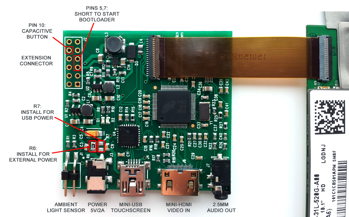
LCD control board is fixed on the back side of LCD and connected to LCD panel by FPC cable:
Powering LCD
LCD with control electronics takes around 1.2A current when backlight is set to maximum value, and it can be powered either by external power supply (5V/2A, jack is OD=2.6mm, ID=0.65mm, positive central pin) or by USB. Power mode is selected by installing one of 0R resistor – R6 for normal power supply or R7 for USB power. CAUTION! Do not install both resistors at once, because this can damage USB port on your computer.
By default we supply LCD with R6 installed, therefore you will need external power supply to run LCD. For USB power you should change 0R resistor from R6 position to R7 position, and make sure that your USB port can continuously provide at least 1.2A current. Power consumption can be significantly decreased by lowering backlight level.
Firmware upgrade
We constantly add new features and provide bug fixes by releasing new firmware for our LCD panels. To update firmware you should start LCD in bootloader mode by shorting pins 5 and 7 on extension header before switching on power, then follow this firmware upload procedure: https://www.chalk-elec.com/?p=1826
New firmware for this 10″ panel is available here: http://goo.gl/wg8WY5
Follow us on Twitter to get instant notification about new firmware release: Follow @ChalkElec
Capacitive touchscreen
LCD touchscreen is based on capacitive technology with up to 10 fingers support, and can work in two modes depending on programmed firmware: single-touch mode and multi-touch mode. We supply LCD with default single-touch mode, because it can work without drivers with any USB host. For multi-touch mode you will need to follow firmware upgrade procedure described above and update Linux/Android kernel as per this How-to: https://www.chalk-elec.com/?p=2028
Ambient light sensor and backlight control
Starting from version 2.0 firmware for our 10″ integrated LCD supports LCD backlight control through standard USB HID protocol and automatic backlight control with optional ambient light sensor. Ambient light sensor should be connected to connector J1, red color wire to pin 1 on connector (pin 1 is marked with white dot). Additional details about backlight control from your host board or PC through USB HID commands are available here: How to control LCD backlight (USB HID).
- Maximum brightness (MAX_BL parameter) is 18 for this 10″ LCD
- Report ID for backlight control is 0x01
Capacitive button
To be added.
